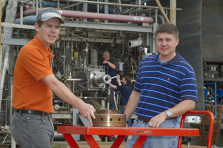
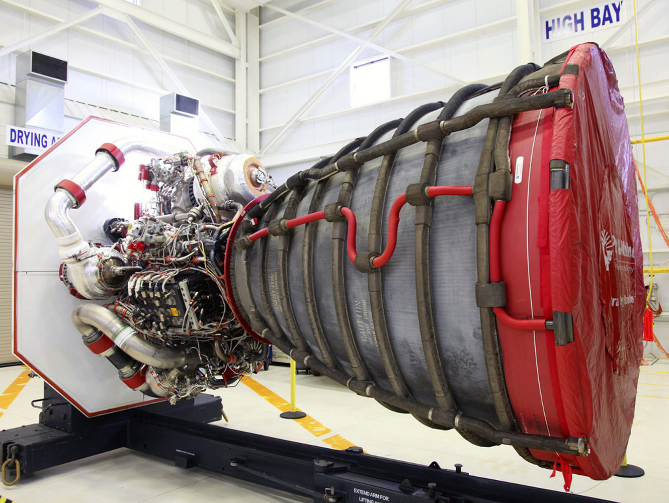
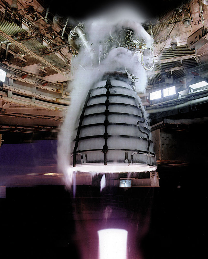
Consider the injector. It’s a lowly little engine part about as big as a basketball, small compared to the more photographic components that surround it. Its job, however, is big. On a rocket, it shoots hydrogen gas and liquid oxygen into a combustion chamber to create the thrust needed to send that rocket into space. It also needs to endure the trip.
A conventional rocket engine injector may be comprised of a hundred different pieces, making it costly to assemble. On an object that costs several hundred thousand dollars per launch, and billions in development costs, any savings are welcome. It’s one reason why the cash-strapped National Aeronautics and Space Administration has been toying around with rocket parts made using an additive manufacturing process, better known as 3D printing.
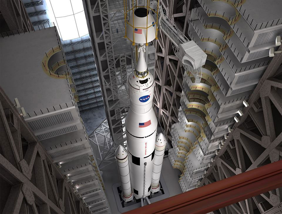
In August, the agency test-fired a 3D-printed injector that withstood a record 20,000 pounds of thrust, which actually isn’t all that impressive. Paired with rocket boosters and the rest, the complete Space Launch System—a new heavy-lift vehicle that will power NASA’s deep-space missions starting in 2017—will create 9.2 million pounds of thrust at liftoff, the equivalent in horsepower of 208,000 Corvette engines revving up at once. What is impressive is the fact that the injector had just two parts and could produce 10 times as much thrust as any previously 3D-printed injector.
For NASA, additive manufacturing represents a way for the agency to stretch its technological capabilities and its $17 billion budget as it looks to build the next class of rocket engines to take its aircraft onto asteroids and to Mars. “The advances in the technology are finally getting to the point where we can see parts additively manufactured for demanding NASA applications,” says Dale Thomas, associate technical director at NASA’s Marshall Space Flight Center in Huntsville, Ala., where NASA has been trying out a variety of 3D-printed propulsion parts for more than a year. What the agency lacks, however, is the knowledge required to judge just how well 3D-printed engine parts will stand up during space flight. “We don’t understand the material properties really well and how they behave under stress,” Thomas says.
Enter the Integrated Product Team, a partnership formed in late May between the Marshall Center, the University of Alabama in Huntsville (as in “Go Chargers,” not “Roll Tide”), and the U.S. Army Aviation and Missile Research Development and Engineering Center, known as AMRDEC. The question at the central of the partnership: Is there a way to 3D-print material strong enough to insert into a working aircraft?
There is good reason to be uncertain about3D-printing parts that can be used in missiles topped with warheads or rockets ferrying astronauts. Which powdered metals will be easiest to print and strongest to deploy? What 3D-printing machines will work the best? The three groups believe that, by pooling their resources and trading notes, they will save time and taxpayer dollars developing additive manufacturing processes useful to the private sector, the military, and space exploration. They also believe they will manufacture higher-quality parts—lighter, stronger—than those created today through conventional machining techniques.
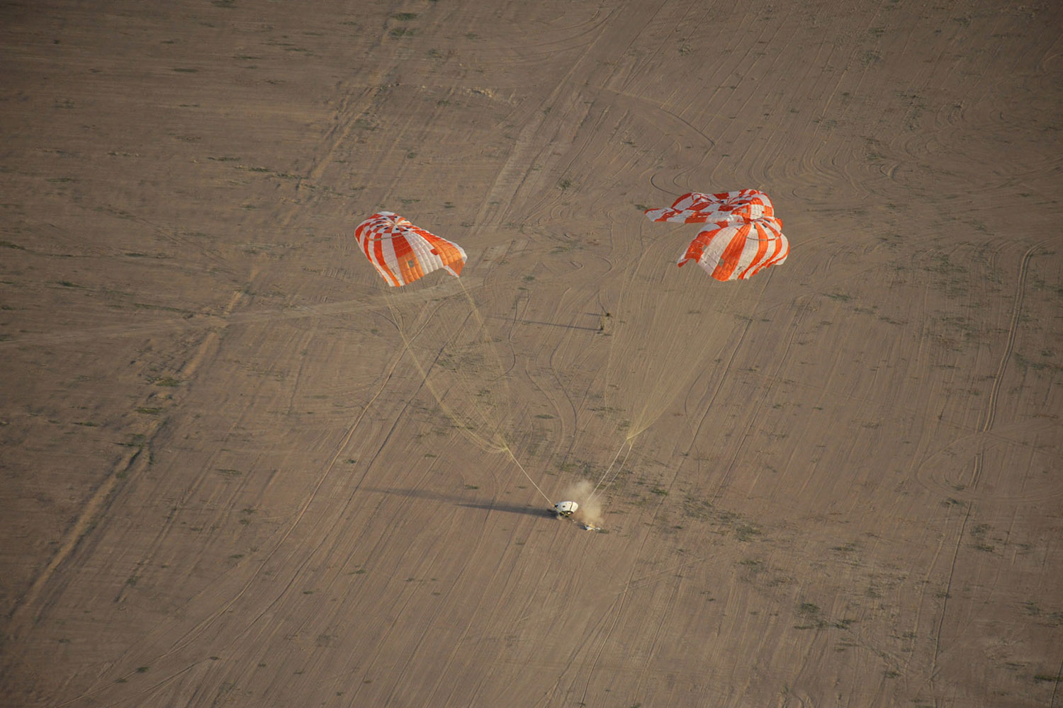
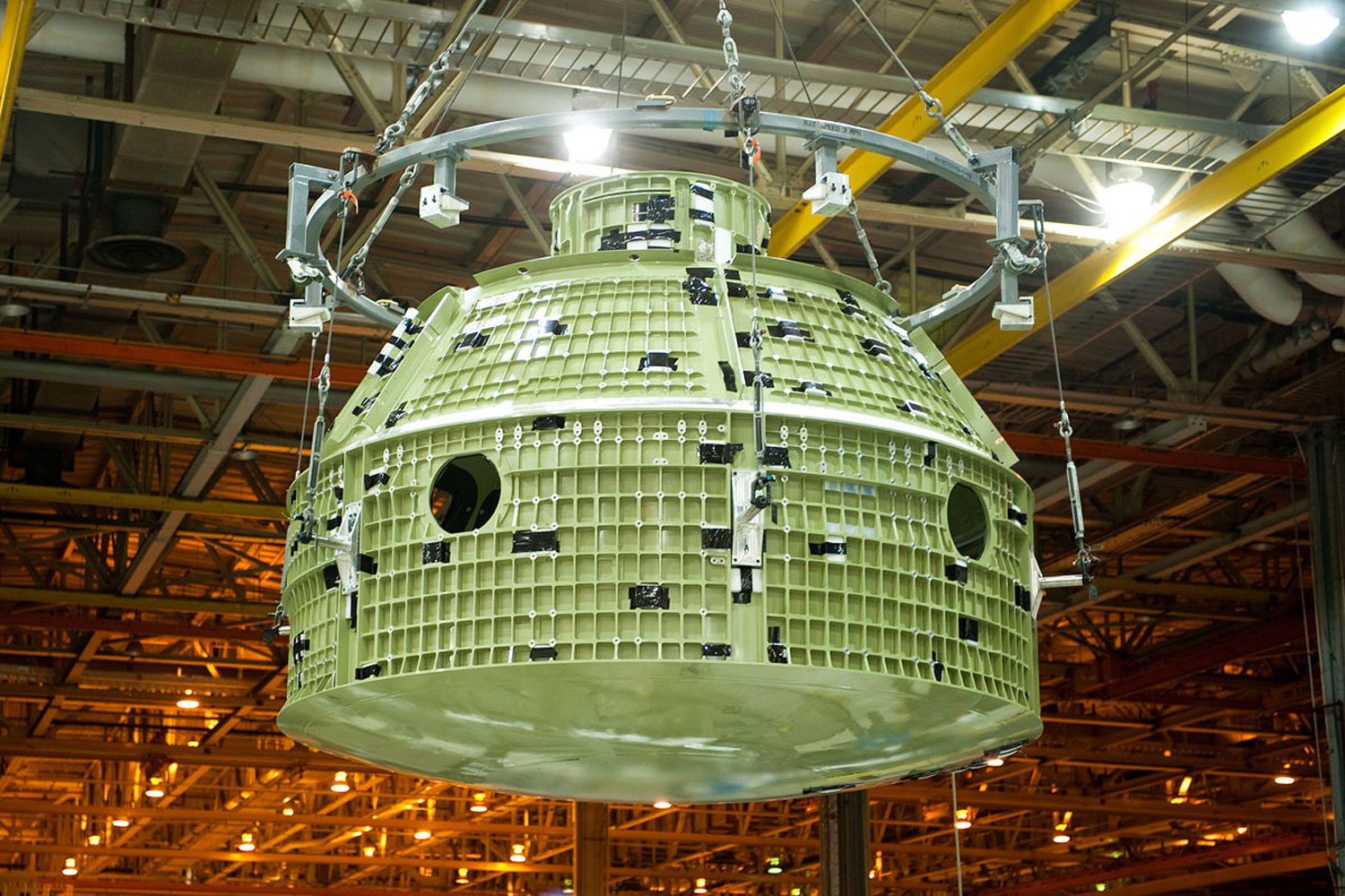
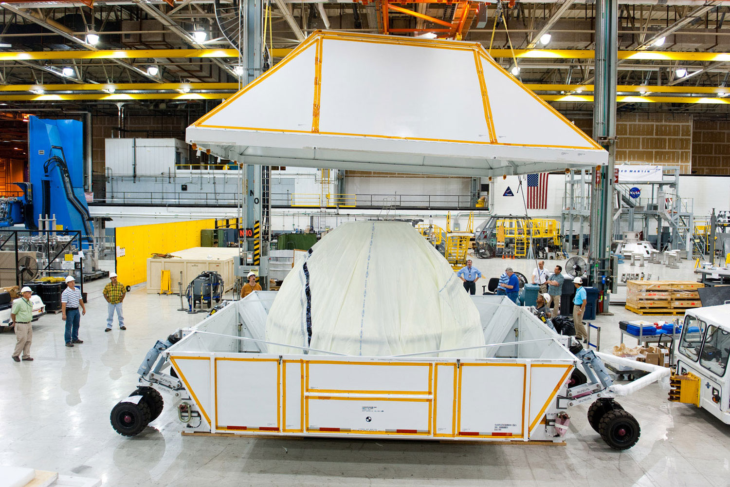
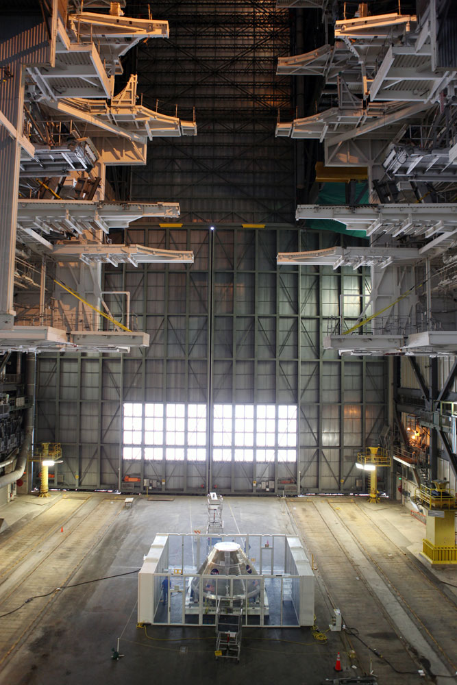
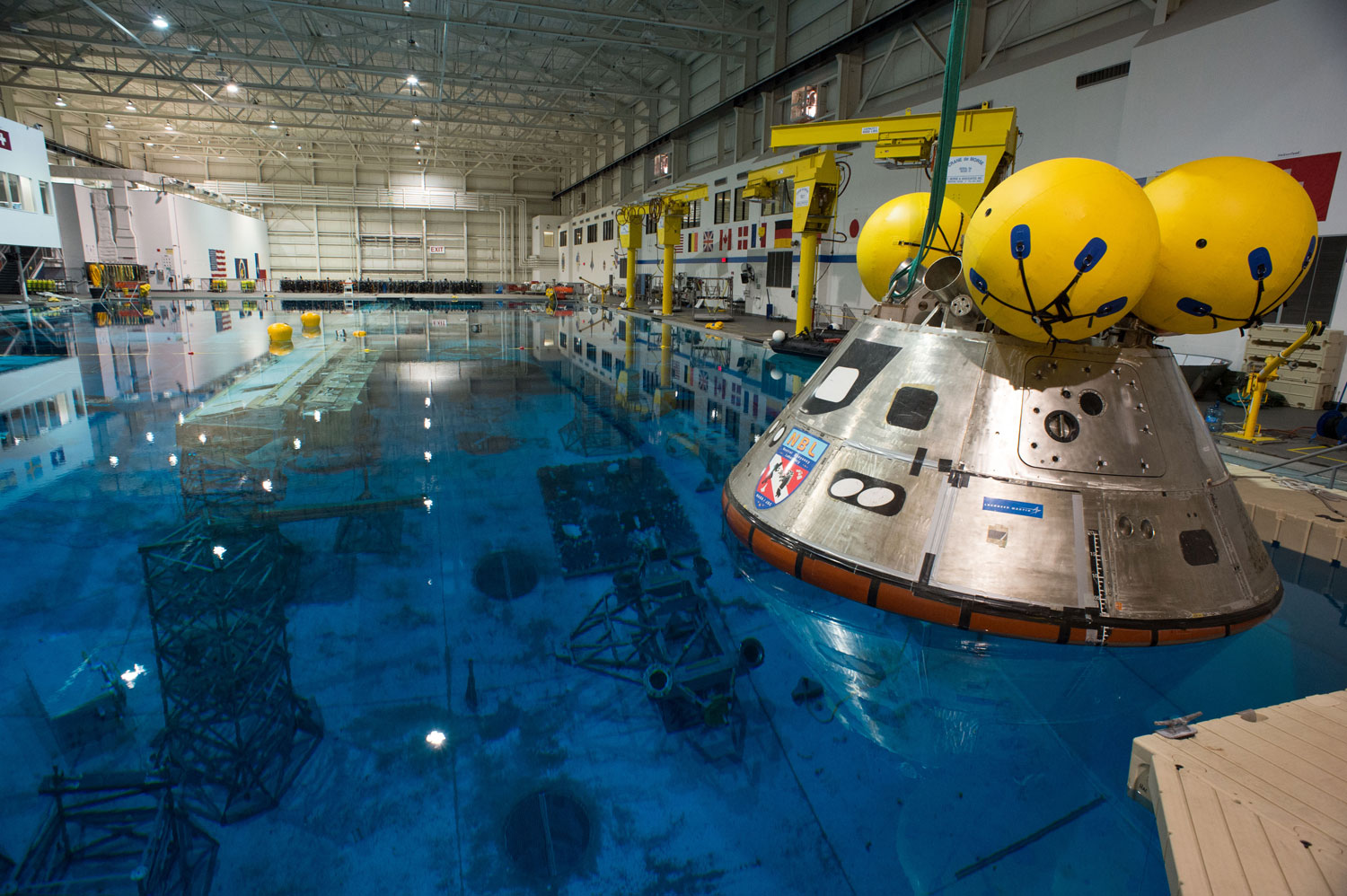
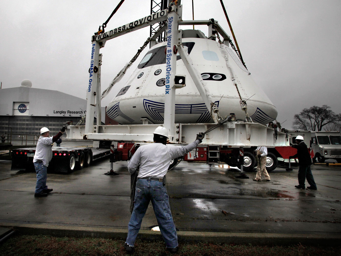
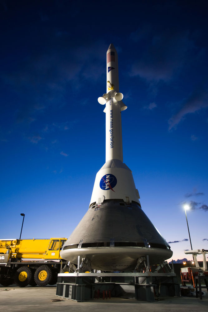
PHOTOS: A Look at America's Next Space Machines


For the military, that means lighter missile components that can still handle vibrations during flight.
“You always want to save weight for an aviation platform. How do you save weight? Machine the part in a way to minimize frequency vibrations,” says James Lackey, acting director of AMRDEC in Huntsville. “Only through additive layering can you take advantage of what a mathematical formula tells you this design solution needs.”
Conventional machining can be thought of as subtractive manufacturing. You begin with a block of some material and gradually chop some off, a process that constrains the types of parts that can be designed. Additive manufacturing is different. Imagine instead a laser-centering machine that heats up and fuses together successive layers of powdered metals—inconel alloys, grades of steel, titanium, aluminum—to construct simpler rocket engine components. This is how NASA created the injector it test-fired a year ago.
“Those little boogers are incredibly complex,” Thomas says. “When you’re trying to manufacture them you throw away more than you use. With additive [we] can make an injector that in the past took about 15 to 20 pieces.”
Lackey and Thomas agree that the space agency’s foray into 3D printing is still in its earliest days. There is no working budget within AMRDEC or the Marshall Center for additive manufacturing experiments because both centers are still determining which 3D-printing technologies they need to invest in. Phillip Farrington, a professor of industrial and systems engineering and engineering management at the University of Alabama, says that whatever knowledge is gained through the Integrated Product Team could also be applied to streamlining manufacturing processes for automobiles, trains, and ships (a research project in which he’s currently engaged).
Right now, the work being done with additive manufacturing at the Marshall Space Flight Center shows the most promise, a reflection of the progress Thomas and his team are making in using the technology to not only manufacture injectors, but also valves, nozzles, and other parts necessary for propulsion in rocket engines.
“We’re seeing parts that can only be made using additive methods,” Thomas says. “We’re never going to get away from the traditional manufacturing process. But additive is going to have some real game-changing benefits.”
More Must-Reads from TIME
- Why Biden Dropped Out
- Ukraine’s Plan to Survive Trump
- The Rise of a New Kind of Parenting Guru
- The Chaos and Commotion of the RNC in Photos
- Why We All Have a Stake in Twisters’ Success
- 8 Eating Habits That Actually Improve Your Sleep
- Welcome to the Noah Lyles Olympics
- Get Our Paris Olympics Newsletter in Your Inbox
Contact us at letters@time.com